Direct connections have been given a big update! Lots of issues were fixed with these types of connections and they are now much more robust as you can see below…
In this update, we also enabled shop-drawing export for SketchUp 2025. However, you need to install 2025.0.3 (or newer). This is because in previous versions of SU2025, a crash could occur when exporting to Layout. But this should now be fixed!
Many users from Europe and other regions that use a comma as decimal separator notified us of an issue that prevented them from being able to create custom bolts. When trying to create a new bolt, they would see an error message. We’ve also fixed this issue in 0.1.5 so all users should be able to create custom bolts now!
To read about all of the changes in version 0.1.5, see the release notes.
We’ve made some tweaks to the previously available AISC, CISC, Europe and Australia profiles. We’ve increased the number of arc segments for the root radius and also made circular hollow sections much smoother. We’ve also fixed tapered flange profiles for the Europe library so that the flange slope angles are now correct.
To update your DECAsteel profile library to the latest version:
Find the email you received when you originally ordered the profile library. Please do not re-order the same profile library.
Click the ‘Go to My Purchase’ button. This will take you to a page where you can download the latest library RBZ file.
Download the library RBZ file and install it using the SketchUp Extension Manager.
Today we released the first version of the Australia Steel Profile library! Thank you to our awesome DECAsteel community members for helping us create this library with care and accuracy.
Get the new library (and more) at our new Steel Library Page. This new library also contains parallel flange channels (PFC) shapes. We are planning to release an update to DECAsteel within the next several days that will allow you to create connection details using PFC shapes. In the current version (0.1.3), connections will not work correctly for PFC members.
I apologize for the long period of silence as DECAsteel development was on hiatus for an extended period. I’m excited to say that we plan to release our first public build (Alpha 0.1) in January!
The first build will be the foundation that we hope to build upon. For this release, we are prioritizing the core structural design / modeling features. Some other exciting features will be available to play with as well (like connections!) but our main goal right now is to create the foundational framework that will allow us to build more features on top of.
Here’s a sneak peak at the main dialog UI, at least how it looks today. Of course, this could change a bit before the release.
It will be great to get this product in front of actual users and start collecting feedback. We’ve got a long way to go but I think you’ll find this alpha release to be incredible useful and a lot of fun to play with! Stay tuned!
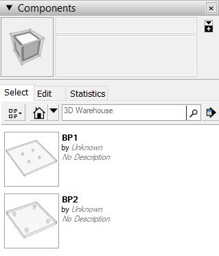
SketchUp really excels at handling discrete repeating objects. The proper term for these are ‘Components’ and they are a key aspect of SketchUp that we will be tapping into with DECAsteel.
Components in SketchUp have some very useful properties:
Each component must have a unique name (sounds a lot like a part number, or mark number doesn’t it?)
Each copy or instance of a component shares a common ‘Definition’. So if you change the underlying entities within the definition, all copies of the component will update automatically.
Components can exist within a hierarchy of objects and can also contain child or sub-components themselves.
Components can inherit the properties (eg. material) of their parent
Considering the above properties, it only makes sense that DECAsteel uses components to manage ‘parts’. We’ll be utilizing Components to generate elements such as:
Baseplates
Bolts, nuts, washers
Connection Plates and Angles
Stiffeners
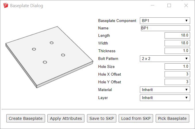
Each of these parts will likely have their own special editing dialog for creating the part and adjusting the parameters of the part. Below is the current state of our Baseplate Editor.
Early dialog for creating a simple baseplate
The dialog currently offers several important features such as selecting, naming, editing, and saving to your local library for future use. As you work with DECAsteel, you will grow your parts library so that you can re-use the various common parts in future projects. Some parts and components will also likely be included with the software.
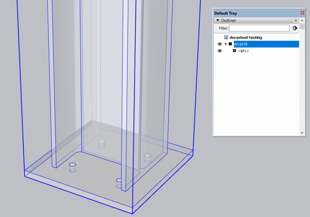
The baseplate component becomes a sub-part of a column since it will typically be handled and tracked as one main object.
Weldments such as baseplates will be child objects (sub-parts) of the main part
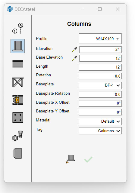
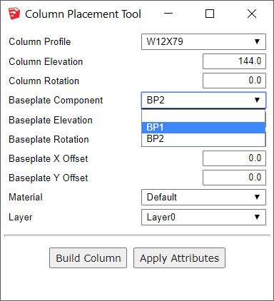
When creating or editing a column, you’ll be able to choose the baseplate from your in-model library of baseplates as shown below in our early Column dialog.
Early column editor dialog
When drawings get extracted to Layout, we will be able utilize Component attributes to create smart auto-text labels and create QTOs and parts lists.
What are your thoughts on components and parts management in DECAsteel? Start a discussion in the DECAsteel Community.
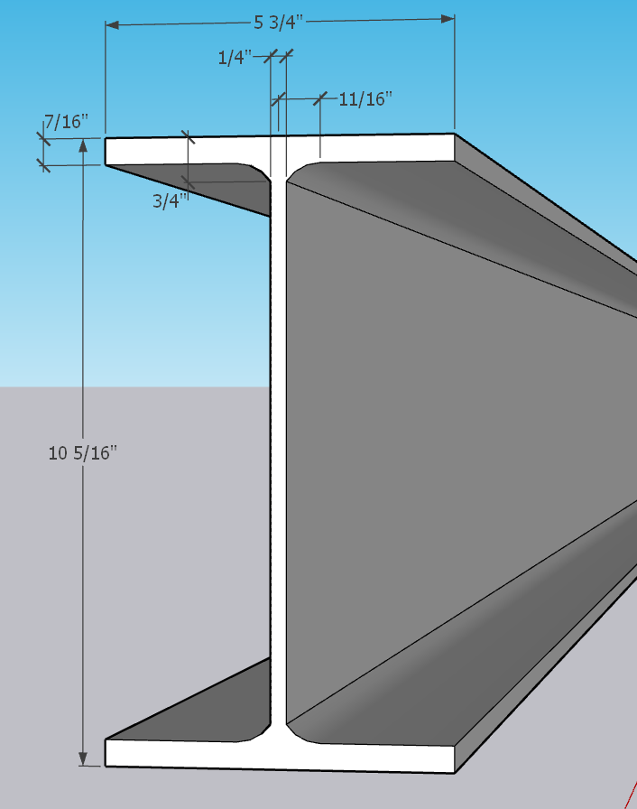
Steel design software without accurate structural profile shapes is pretty much useless. It’s not enough for an AISC W10x26 beam profile to match the nominal height and width of 10 and 6 inches respectively.
For accurate design and connection detailing, we needed to take it a step further and develop a tool for importing an entire database of standard steel profiles into SketchUp while taking into account the profile area, weight, flange thickness, web thickness, k, and k1 values.
One of the first tasks we worked on was to create a Structural Shape Importer. I’m not sure yet whether this tool will be ‘internal only’ or if it will become part of the public version of DECAsteel, but it allows us to import accurate structural profiles into DECAsteel from any source / standard whether from CISC, AISC, British, Australia, German, Chinese, it doesn’t matter.
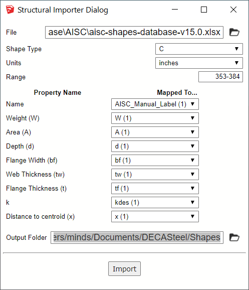
The only requirement is that the key properties of the shape are saved in an Excel spreadsheet. Here’s how it works:
Select your database Excel file
Choose the shape type you want to import (C, L, I, S, Tube)
Map the key shape properties to the columns in the spreadsheet
Click the import button
In a few seconds, the DECAsteel shape library will be imported and ready to use to create beams, columns, and bracing and you never need to question the accuracy as long as the original Excel file was created by a reliable source.
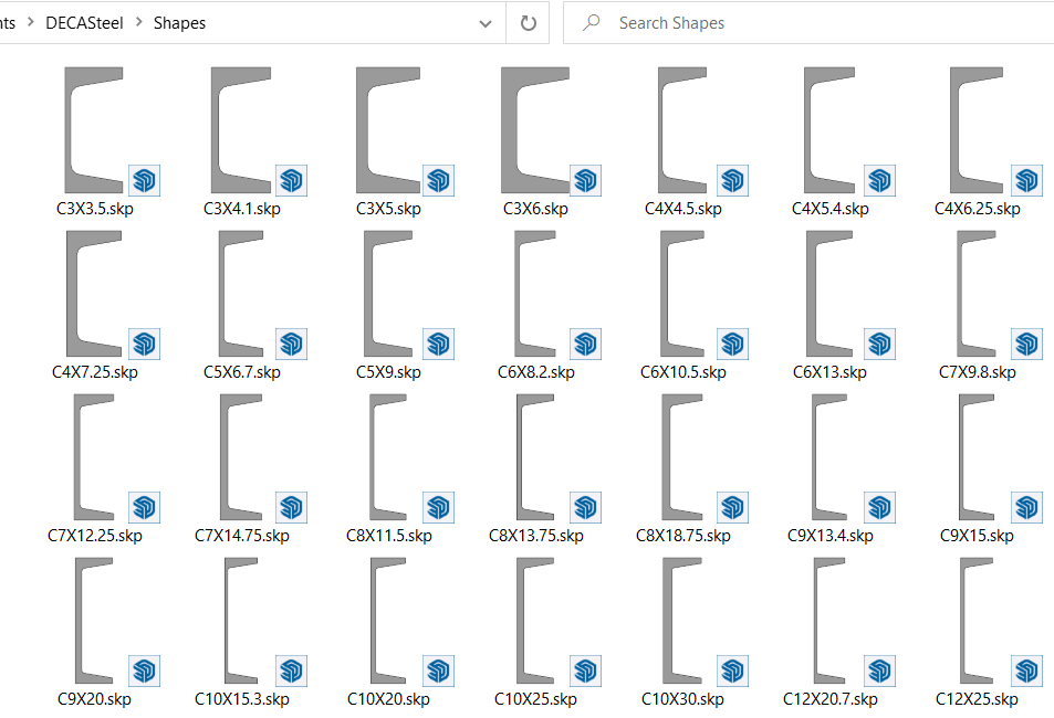
Importing C-shapes from the official AISC database
A portion of the database to be imported
After importing, each shape is saved as a SKP file which can be utilized by DECAsteel
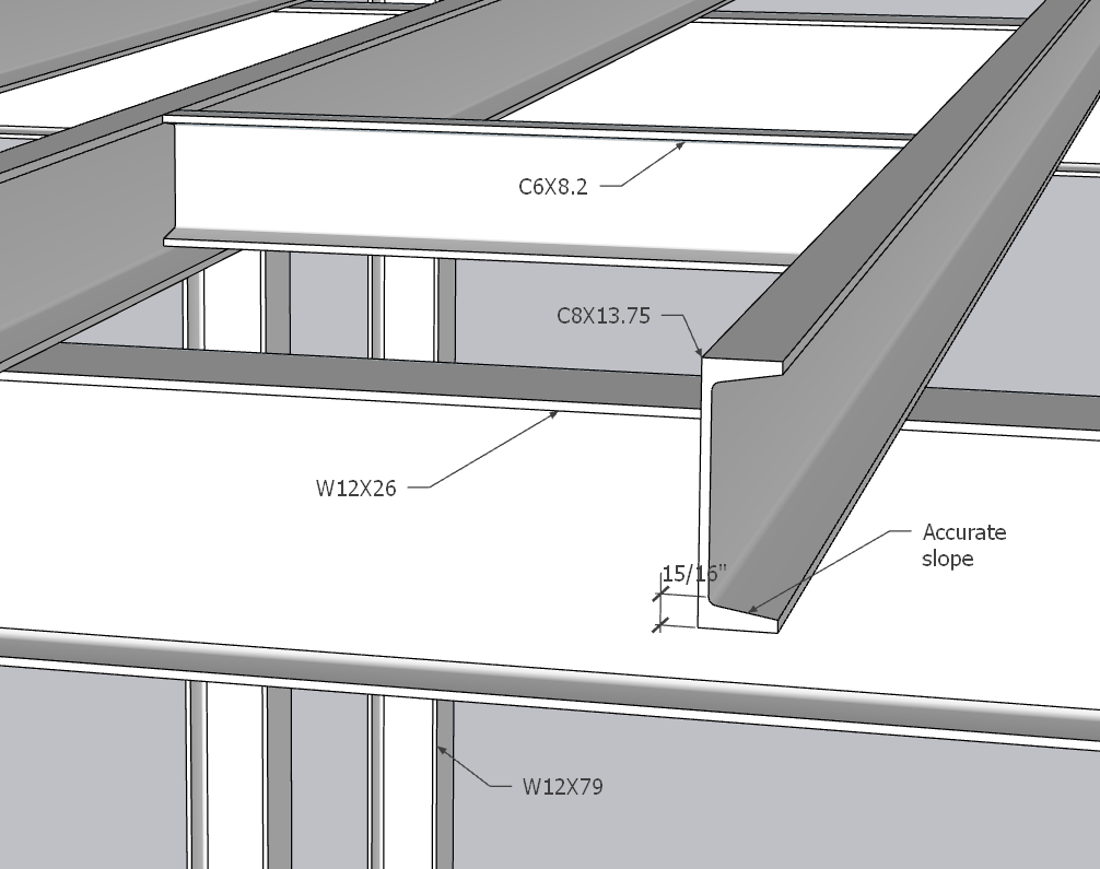
With the shapes imported, I can now use them to model my structure and detail the connections using DECAsteel.
The newly imported C-shapes are used to model some beams.
There are a few challenges still remaining for us:
Tracking down and obtaining permission from various design authorities throughout the world to utilize their database with our software
Determining if there are more key properties that should be imported besides the ones shown above
Determining if it is important to maintain a consistent root radius when dealing with k and k1 values. It seems that radii can vary depending on the steel manufacturer so the actual radius value appears to be not a critical design element.
For C-shapes, the database gives the average flange thickness how is this actually calculated? Is it based on the standard bolt gage location? Or is it based on mid-way between the inside face of the web and tip of the flange? Or maybe something else?
If you have any insight into the items above or have any other feedback about this topic, we’d love to hear from you. Please leave a comment below or start a discussion in our Community Forum.
I want to bring you all on a journey that began in 1998 when I was trying to decide whether to pursue a career in Structural Engineering or enter the field of Computer Science and pursue software development. I ended up choosing Engineering and, after 4 years of university, worked as a Structural Engineer up until 2016. It was then that I decided to leave my relatively comfortable career and make the leap from developing SketchUp plugins as hobby / side business to a full time gig. This has turned out to be one of the best decisions of my life!
DECAsteel™ was first conceived sometime around 2012 when I was beginning to use SketchUp more and more in my structural engineering work. I loved using Profile Builder to design and visualize my structural steel designs in 3D. Most engineers in my office were still using pencil sketches and red-lines to exchange design information with the Structural CAD Tech, a process that had always bothered me due to its proneness to errors. I always tried to focus my designs on constructability and efficiency. Creating the steel design in 3D provided huge advantages in those areas.
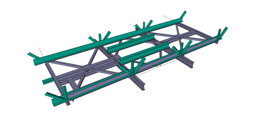
This image is from one of my old engineering projects modeled using Profile Builder. I created engineering sketches from this partial 3D model that were used to perform field repairs for this gallery structure.
Partial model of a gallery over a thickener tank
Having become familiar with many different steel design and analysis tools over the years, I always thought it would be so great if I could create a steel design extension for my beloved SketchUp. There’s just something about creating 3D in SketchUp that no other application could ever match. It’s hard to describe, but if you are a passionate SketchUp user like me, you know what I’m talking about.
As a structural engineer, I desired fast and efficient structural steel 3D modeling tools that would allow me to quickly visualize a design and catch interferences and constructability issues as early as possible. I didn’t want to have to wait for someone else to model my paper sketch in 3D before finding out that there was a deal-breaking problem!
Another issue that always bothered me was having to re-create my designs in multiple applications which leads to errors each time the design is exchanged. For example, a common workflow would be for the design to be rough-sketched on paper, then modeled using structural analysis software, then sketched again on paper with updated member sizes and dimensions. Next, the design sketch would be given to the CAD Tech to model in 3D or draw in 2D (yes, we still used 2D for many projects!) It just wasn’t very efficient.
Certain jobs called for a very quick turnaround as well. Field sketches might be needed during construction to solve an interference problem. Or an urgent structural repair needed to be done on site. There was no time for mistakes! So often, I felt limited by the software that was at my disposal at the time. Solutions like Tekla and ProSteel were too complicated and far too expensive. There had to be a better way!
With DECAsteel™, our mission is to create the most cost-effective and efficient set of tools for communicating the design of structural steel between the engineer, the shop, and the project team. It is an ambitious goal but one we are ready to strive for!
We hope you will join us in this mission by sending us lists of features that would be especially important for your own personal steel design workflows and by giving us feedback on the features that you see us working on (we plan to share our development progress often!) Make sure you sign up to receive our development newsletter on the home page, and to get in touch with us, just submit a request at the community forum.